ASTEP : Telescope & Focal box [from Mekarnia et al. 2016, MNRAS, 463, 45]
Telescope
ASTEP 400 is a custom 40 cm Newtonian telescope with a sophis- ticated field corrector, designed to withstand both Dome C summer and winter temperatures ranging from −20°C to −80°C with rapid variations. The primary mirror diameter is 40 cm with a focal ratio of 4.6. Because of its wide FoV (1° × 1°) and of the layout of the optics and cameras in the focal box, the secondary mirror is quite big (23.5 cm × 16.5 cm) leading to a central obstruction of 42% in radius (18% in surface). Both primary and secondary mirrors are made in glass ceramic material Zerodur and coated with protected aluminium. Even if a better reflectivity is provided with silver coatings in the red, we choose aluminium because it provides enhanced protection in harsh environment. Another important aspect is that recoating a mirror is impossible on site and we do not have any experience with silver coating in such harsh climatic conditions. Protected silver is generally more fragile than aluminium, in particular in the presence of condensation. However, people used to believe that the absence of dust and the low vapour content would prevent the coating degradation. No experiment has been undertaken so far to check that assumption. Therefore, we preferred a more conservative approach for ASTEP. The mechanical structure of the telescope is an eighth-order Serrurier truss with carbon fibre legs, connected to an aluminium alloy main frame through Invar sleeves to achieve a good thermal and mechanical stability of the instrument.
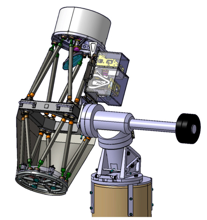
Engineering model of ASTEP 400. The mechanical structure of the telescope is an eighth-order Serrurier truss. The main frame in the middle of the structure and both its upper (the secondary mirror spider assembly) and lower part (the primary mirror barrel assembly) are made of aluminium. The hollow bars that link these three parts are made of carbon fibre with InvarTM sleeves at each end. The telescope mount is a commercial equatorial AP3600 from Astro-Physics Inc. that we have adapted to withstand the harsh Antarctic conditions.
The telescope structure is covered by a two-layer envelope to protect optics both against stray lights and ice dust deposit. Finite element analysis was carried out to predict the deformations of the structure depending on the telescope positions and temperature variations and their impact on the point spread function (PSF) quality and stability. Even with this careful design and manufacturing, the thermal expansion during rapid temperature variations may yield a telescope defocus of ∼150 μm for a temperature variation of 30°C, with a telescope focal length of 1860 mm. This is equivalent to a PSF full width at half-maximum (FWHM) widening of 50 per cent.
The telescope and the focal box camera were designed, developed and constructed by our team, while the telescope mount is a commercial equatorial AP 3600 from Astro-Physics Inc. that we have adapted to the harsh Antarctic conditions (e.g., by changing the grease, heating the drive motors and by modifying a few mechanical components). Since the telescope is observing almost continuously, the mount is re-winded automatically, when it exceeds two or three spins, to prevent winding of the connection cables.
Focal box
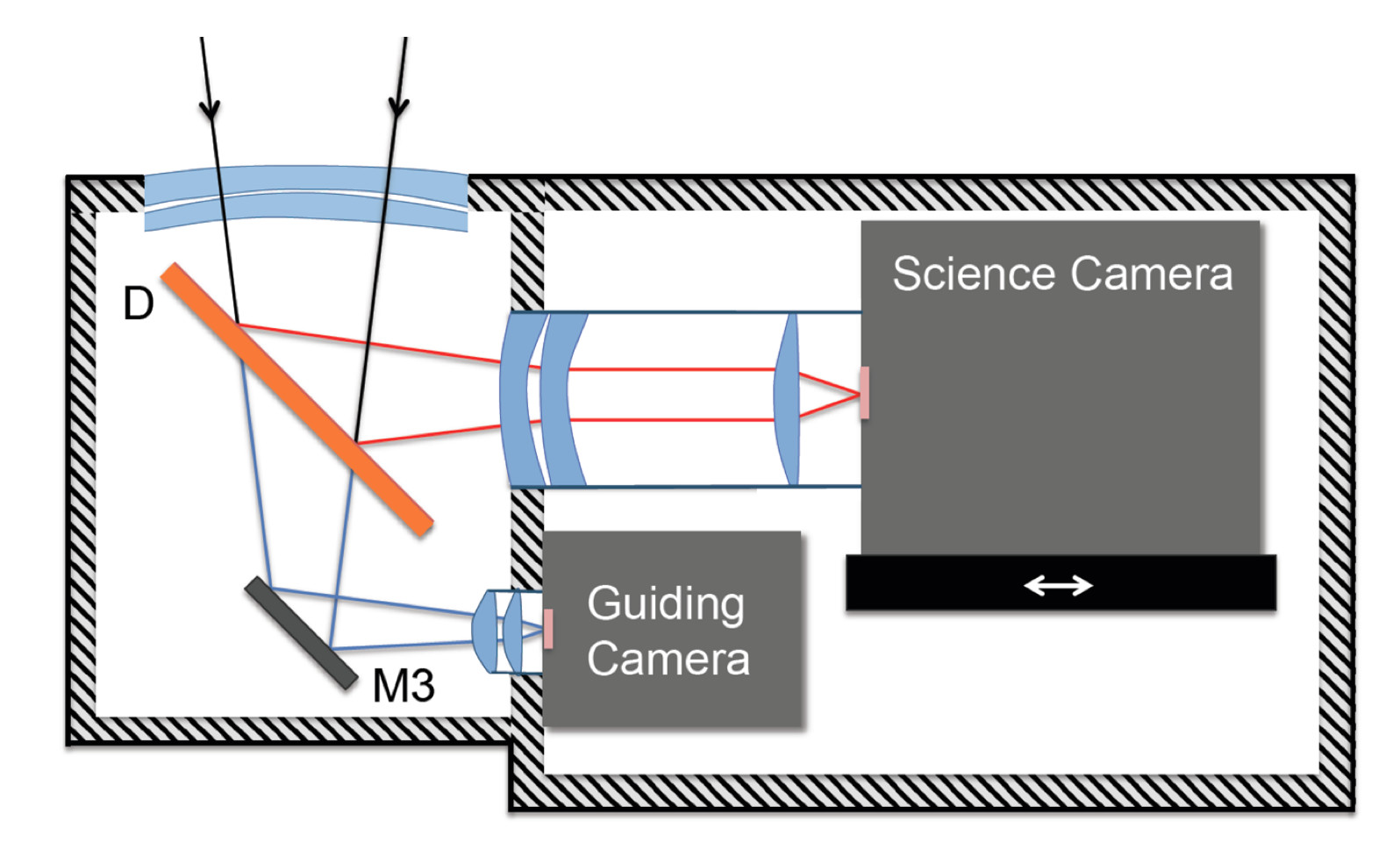 Optical design of the focal box. Light coming from the Newtonian flat secondary mirror through the double-glazed optical window is split into two beams by the dichroic plate (D) which reflects the red part to the Science camera and transmits the blue part to the Guiding camera through the mirror M3. The two first lenses of the optical window, along with the three other lenses, located between the dichroic plate and the Science camera, contribute to the field coma correction. The Science camera is mounted on a remote- controlled translation stage to get the proper focus.
The focal box is divided into two compartments. The first compartment contains only optical components, the dichroic plate (D) and M3 mirror, while the second compartment contains the ‘science/guiding’ cameras, the motorized translation stage and their electronics. The focal box receives the in- coming beam from the Newtonian telescope’s flat secondary mirror through the two first lenses of the five-lens Wynne coma correc- tor, which act as a double-glazed insulation window. These lenses, along with the three other lenses located between the dichroic plate and the Science camera, contribute to the field correction yielding an excellent image quality over the 1° × 1° FoV. The PSF deformation across the field is negligible compared to the mean FWHM which is of 2 arcsec in good seeing conditions.
The focal box is mounted on a carbon fibre plate ensuring its rigidity and thermal stability. The opto-mechanical mounts are in titanium alloy chosen for its low weight, high mechanical resistance and low thermal expansion coefficient. The dichroic plate (D) separates the Science path from the telescope guiding path. The red part of the spectrum (λ > 0.6 μm) is sent to the Science camera, while the blue part (λ < 0.6 μm) is directed to the Guiding camera. No filter is used and most of the signal is transmitted in the red. The Science camera is a 4096 × 4096 pixels front-illuminated FLI Proline KAF 16801E CCD with a 16 bits analogue-to-digital converter. The CCD dimension is 36.8 mm × 36.8 mm and the plate scale is 0.93 arcsec/pixel (1 pixel = 9 μm). The Science camera, which is cooled by a Peltier device, is mounted on a MICOS remote-controlled translation stage, which has a positioning accuracy better than 1 μm. In practice, the optical best-focus estimation cannot be better than 5 μm. The system was designed to be slightly defocused and spread the PSF FWHM to about 3 pixels reducing the noise due to jitter and inter-pixel variations. The actual optical train suffered an on-axis astigmatism that did not allow PSF FWHMs better than 2 arcsec; thus, no defocusing was necessary. On the contrary, this astigmatism was used to find the right focusing direction (inward or outward). The Science camera can be removed and replaced with an He–Ne laser for the optical alignment of the whole instrument. The optical combination has been calculated to ensure a stable and homogeneous PSF from the centre to the corners of the CCD, with an FWHM below 3 pixels when atmospheric turbulence is low and stable. This is not always the case because the entrance telescope pupil is at about 2 m above the ice surface, which is far from optimal seeing conditions at Dome C. The Guiding camera is an SBIG ST402M ensuring, in normal observing conditions, a guiding stability of about 0.2 arcsec rms or better.