The Twin Impact Lunar Telescope (TILT)
On July 1st, 2025 the fist Twin Impact Lunar Telescope (TILT-1) was installed in the dome "Picard Sol" at the Calern Observatory. It is equipped with two 400mm f/4.25 newtonian telescopes (carbon fiber) manufactured by optician F. Giacometti in Italy. These tubes are co-mounted on a custom modified REOSC fork
Telescope & Camera system
For this project we use a home-built 0.5 m diameter f/D=6 telescope. The primary mirror has a parabolic shape and has been donated to us by George Viscardy’s wife. We “bent” the 3 m-long focal length using a 21 cm diameter flat secondary, crafted by Romano Zen in Venice Italy. The focus position lie sidewise of the truss at about 0.6 from the primary mirror surface.
The tube truss and equatorial fork mount were crafted by Silvano Delbo, in Novi Ligure, Italy. The mount uses a dual stage friction drive on both axis such that no gears are used. The axes are driven by high resolution, 1000-steps per turn Oriental Motors steppers, which provide a very smooth and silent operation. Motors are driven by an Arduino Zero. Home build absolute encoders are installed on each axis, which are used for safely limits and pointing the telescope. The concept of these angular encoders and their calibration is described below.
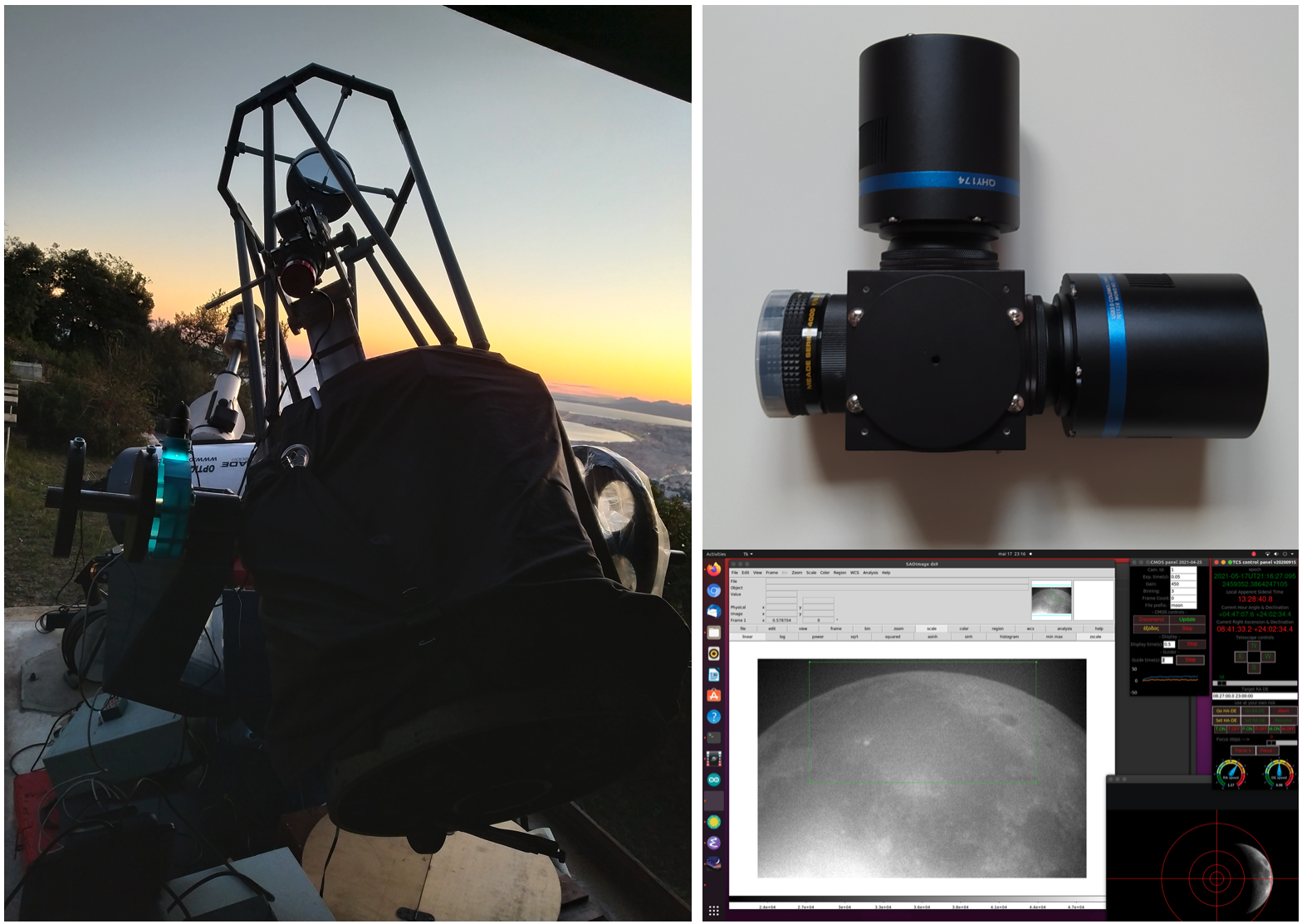
During the initial testing observations a 183 AZI ZWO CMOS camera was used. The updated system is a double camera with 2 QHY 174 CMOS cameras and a dichroic beam spitter. The two cameras can be synchronised by an integrated GPS system.
Concept of the angular encoders: The absolute encoders used for this project are based on the very simple concept of comparing an image of a mobile ruler from a fixed camera. The latter is implemented with a low-cost commercial USB microscope, which illuminates the ruler by means of its LED headlights. The ruler is made by vertical black-and-while lines, which position is random. Hence any location on the ruler is different than any other one. The camera sensor’s column are approximated aligned with the ruler’s lines. The columns of each image taken by the USB camera are summed resulting in a 1D array of pixels, which is cross-correlated with a ruler template. The position of the maximum of the cross-correlation indicates the position of the centre of the image along the ruler. As the ruler moves, said position changes. Slight misaligned of the ruler’s lines compared to the camera column is not a problem, resulting in broadening of the 1 D line profile. Sub-pixel accuracy can reached, by fitting a parabola on the magnitude of the cross-correlation function around its maximum and determining the vertex of the parabola. When the ruler is wrapped around a disk, angular displacements of the latter, corresponding to liner displacement of the ruler with respect to its image template, can be measured. It is hence possible to measure the angle of the disk.
Construction of the ruler template: The method is scale dependent and is based on the idea that the template of the ruler against which each image is cross correlated is constructed from the images themselves. This procedure begins by defining a very long e.g. 50,000 pixels, 1 D empty template and a-same-length scoring template of integers. The ruler and scoring template are initially equal to zero for all pixels. Next, a scanning of the entire ruler by the USB microscope camera is performed. Several images per second are taken, while the ruler is displaced by a small amount between each image in the positive direction. The sum of the column of the first image is added to the ruler template by shifting its centre to image-width/2 and one is added the corresponding pixels of the scoring template. The sum of the columns of the each next image are cross correlated with the sum of the columns of the previous images and an integer shift is between image n and image n+1 is calculated. The sum of column of the image n are thus added to ruler template. When the template of the entire (or usable section thereof) has been acquired, it is divided by the scoring 1D array (in order to calculate a mean) and the result is saved in a file. The build-ruler.py python3 code is used for the construction of the ruler template (it requires SAOImage ds9 and the XPA library to be installed amongst other things; see import session).
Operation of the encoder: Images of the ruler are acquired with a typical frequency of 10 per second from the USB microscope (using the openCV python3 framework). After some processing the sum of column of the image is cross correlated with the ruler template and the position of the maximum is used to determine the center of the image along the ruler. This procedure (test-ruler.py) return a scalar position in pixel along the ruler. In order to transform pixel to sky coordinates a calibration of the ruler is needed.
Ruler calibration on the sky: This consists in determining an appropriate transformation that allows one to convert encoder ticks in coordinate on the sky and viceversa. This is achieved by taking images of the sky with the telescope and using a plate solving algorithm to determine the sky coordinates of the center of the field. These coordinates are corrected for the equinox precession and transformed to local hour angle (tau) and declination (delta). The encoder position during the acquisition of each image are also recoded, such that for each image taken on the sky there are sky coordinates (tau and delta) and the two encoder pixel positions.